Elements of Excellence… Quality Engineering for your High-Tech Products
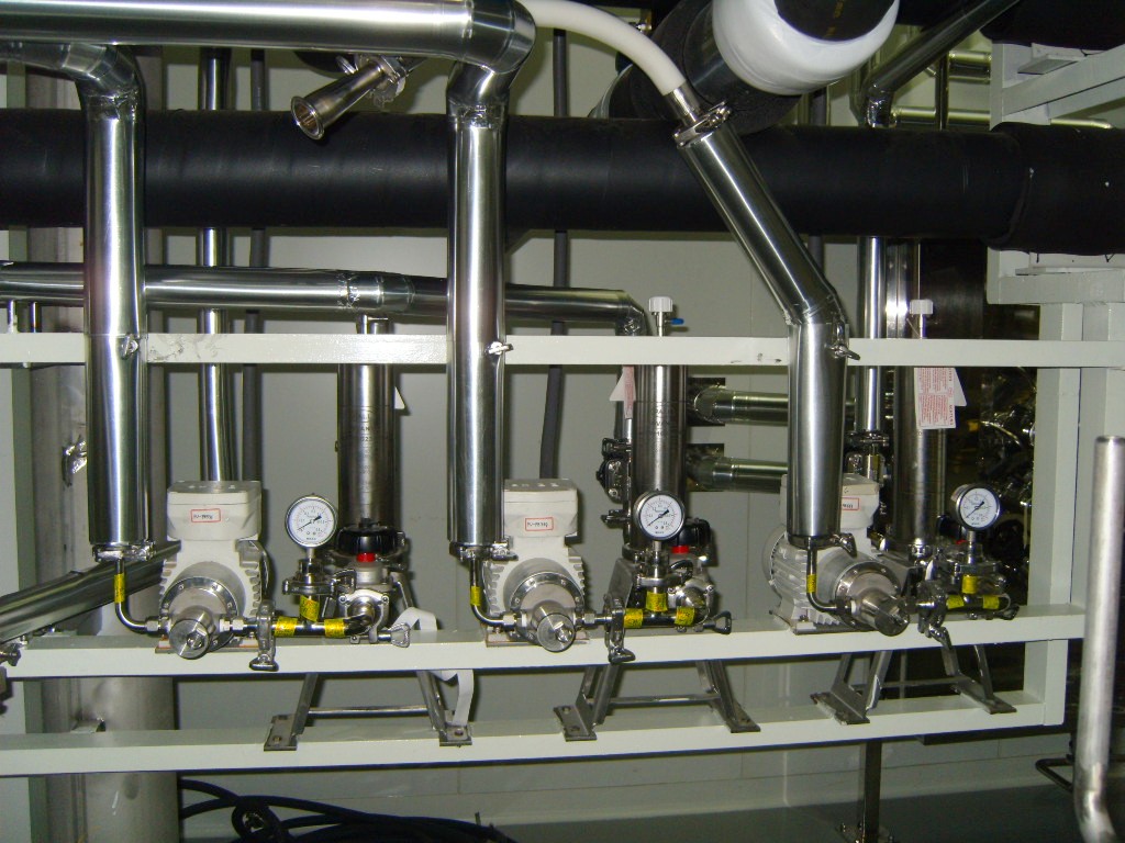
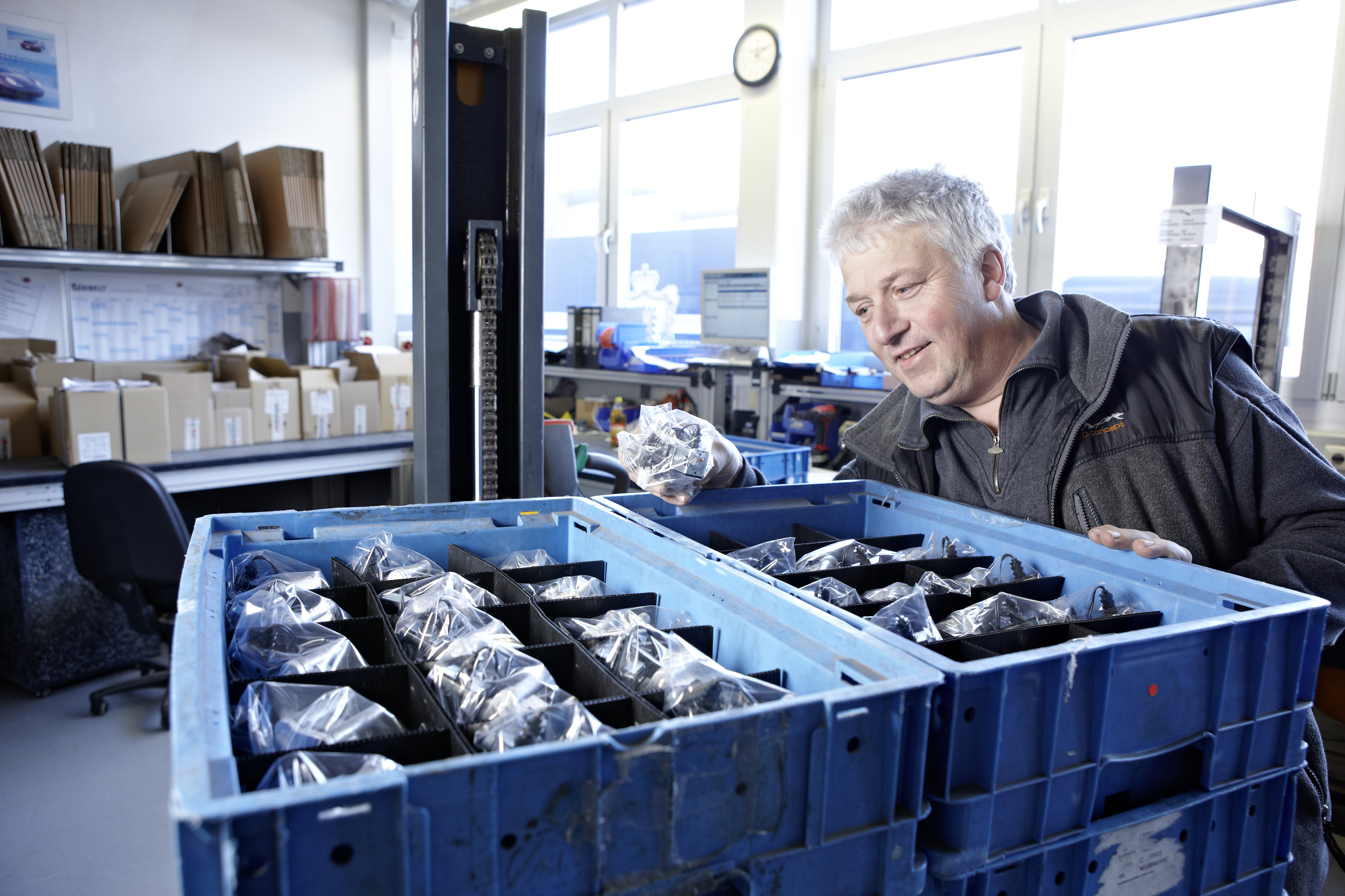
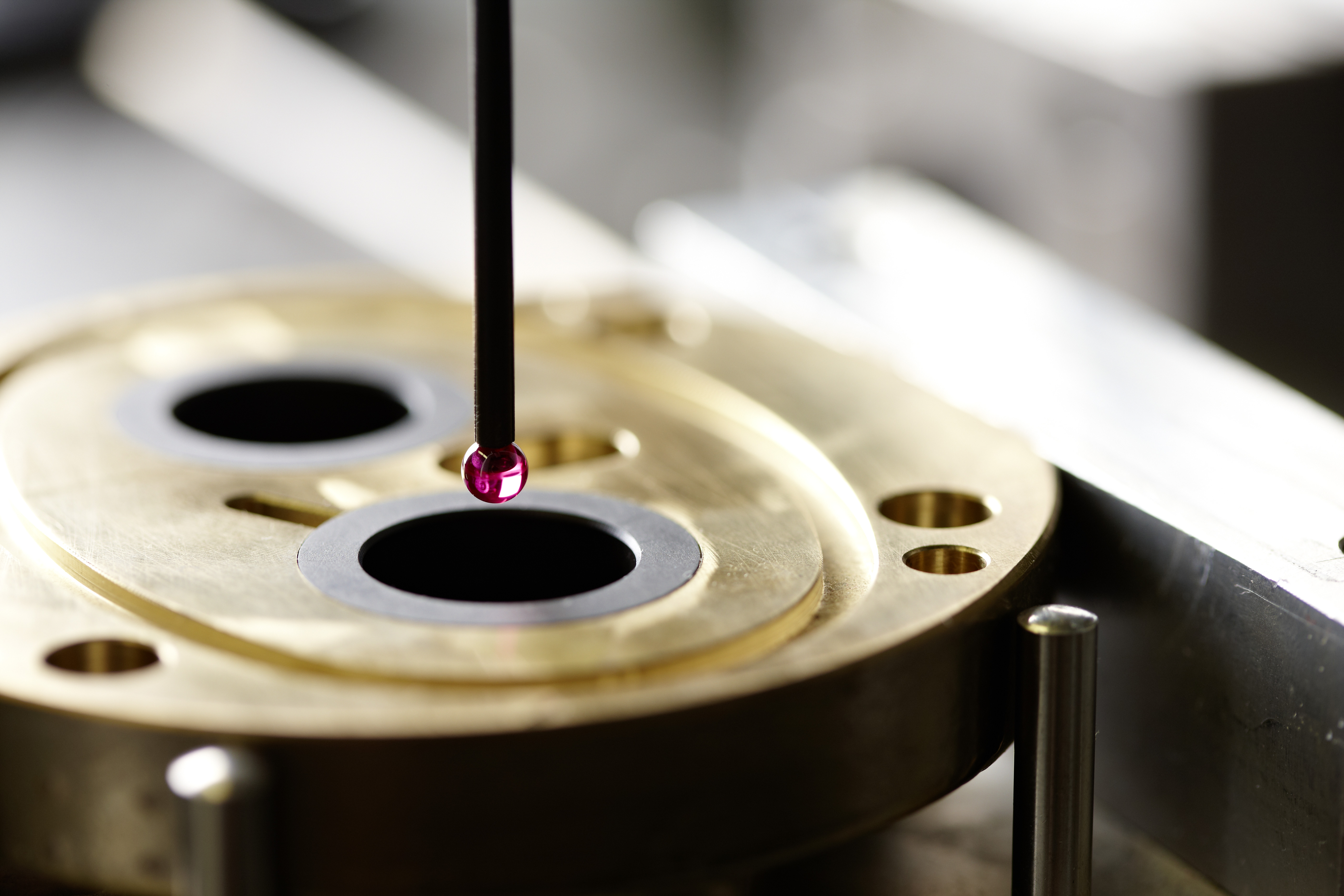
We design and produce our own manufacturing tools to insure that each integral component meets our high stndards of precision and quality. Our certified QS management System guarantees our clients the utmost in quality assurance.
While Scherzinger is active in many industries, our focuts here at Consolidated Turbine Servies is to help support the Flow Divider and Shear Seal Valve products lines.
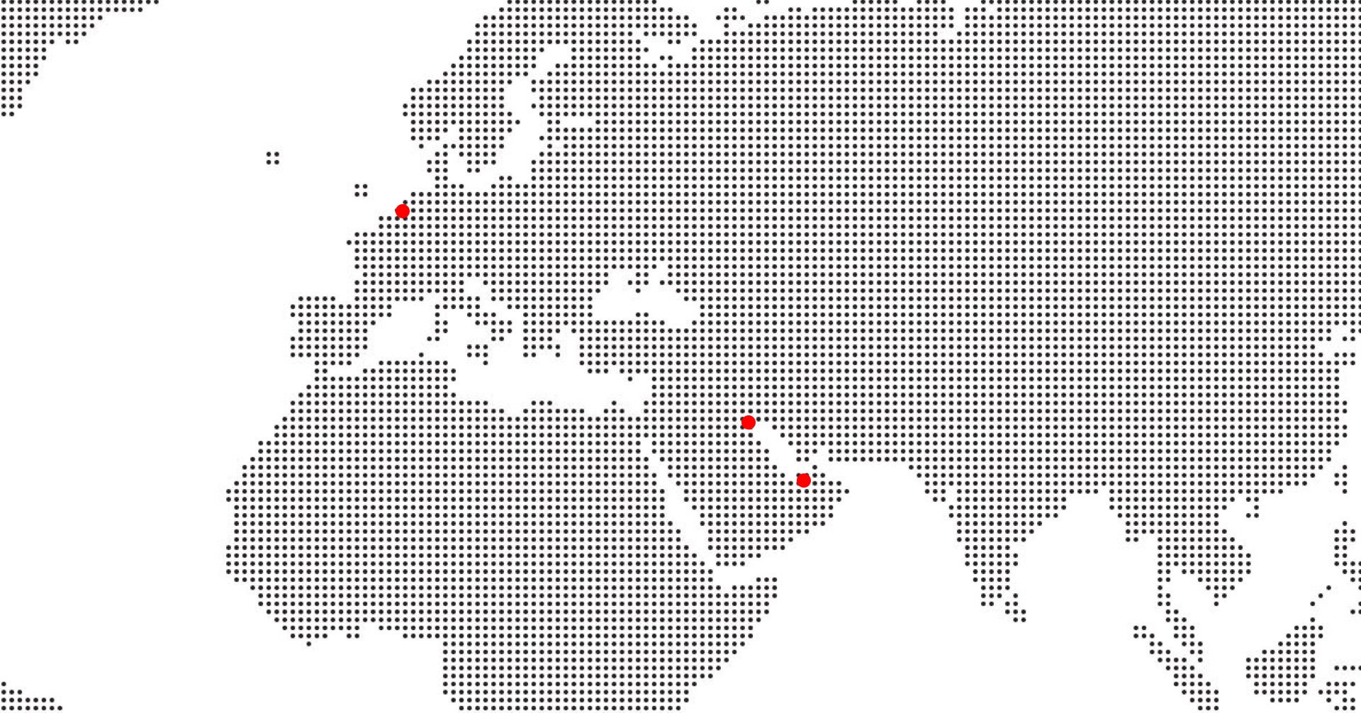
Our customers for these products are active in the Power Generation and Oil & Gas industries, utilizing Scheringer products to deliver consistent fuel to Gas Turbine firing chambers.
Some of our customers include DUBAL, SEWA, ADWEA, STOMO, GEEP and many other customers in the region.
Some of our customers include DUBAL, SEWA, ADWEA, STOMO, GEEP and many other customers in the region.
Consolidated-Turbine Services has been working with Scherzinger since 1989; providing our customers in the Middle East with full technical and commercial support for Scherzinger products.


LINEAR SINGLE ELEMENT FLOW DIVIDER
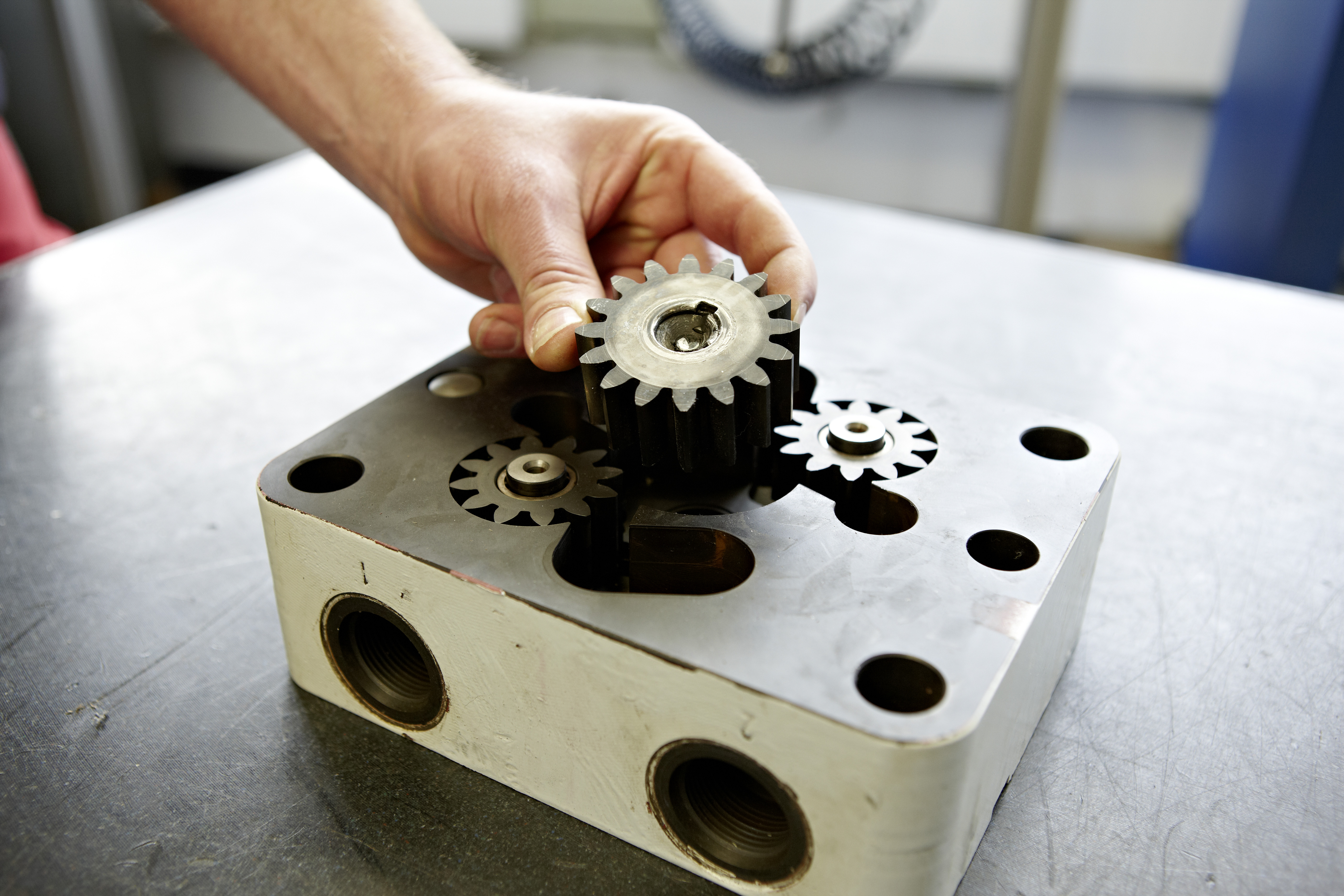
The Flow Divider Consists of multiple gear pump elements with a single inlet and multiple outlets in a linear arrangemnet.
All gear pump elements have on drive gear and one driven gear, rotating in the gear chamber with small diametral and lateral clearances.
Every drive gear is connected to the other by coupling bushes to synchornize ths peed of all gear pump elements.
Each gear pump element is driven by the fuel stream and therefore directly proportional to the speed of the flow divider.
As a consequnce each fuel nozzle of the gas turbine is provided with the same quantity of fuel.
| Designed For | All GE Fram 5 and GE Frame 6 |
| Number of Elements | 2; 4; 6; 10; 12; 14; 18 |
| Flow Rate per Element | 12.8 l/min (3.4 GPM) at 2400 RPM |
| Operating Pressure | Max 103 bar (1500 psig) |
| Fuel Temperature | Max 130 ºC (266 ºF) |
| Fuels | Distillate, Heavy Fuel, Crude, Naptha |
| Starter Motor | Optional (available in various types. |
LINEAR DOUBLE ELEMENT FLOW DIVIDER
The Flow Divider Consists of multiple gear pump elements with a single inlet and multiple outlets in a linear arrangemnet.
All double gear pump elements have on drive gear and two driven gears, rotating in the gear chamber with small diametral and lateral clearances.
Every drive gear is connected to the other by coupling bushes to synchornize ths peed of all gear pump elements.
Each gear pump element is driven by the fuel stream and therefore directly proportional to the speed of the flow divider.
As a consequnce each fuel nozzle of the gas turbine is provided with the same quantity of fuel.
| Designed For | All GE Fram 5 and GE Frame 6 |
| Number of Elements | 2; 4; 6; 10; 12; 14; 18 |
| Flow Rate per Element | 12.8 l/min (3.4 GPM) at 2400 RPM |
| Operating Pressure | Max 103 bar (1500 psig) |
| Fuel Temperature | Max 130 ºC (266 ºF) |
| Fuels | Distillate, Heavy Fuel, Crude, Naptha |
| Starter Motor | Optional (available in various types. |
CIRCULAR FLOW DIVIDER
The Flow Divider Consists of multiple gear pump elements with a single inlet and multiple outlets in a circular arrangemnet.
All double gear pump elements are equipped with two driven gears, rotating in the gear chamber with small diametral and lateral clearances.
Every driven gear is connected to the other by a central sun gear to synchronize the speed of all gear pump elements.
Each gear pump element is driven by the fuel stream and therefore directly proportional to the speed of the flow divider.
As a consequnce each fuel nozzle of the gas turbine is provided with the same quantity of fuel.
| Designed For | All GE Fram 5 and GE Frame 6 |
| Number of Elements | 2; 4; 6; 10; 12; 14; 18 |
| Flow Rate per Element | 12.8 l/min (3.4 GPM) at 2400 RPM |
| Operating Pressure | Max 103 bar (1500 psig) |
| Fuel Temperature | Max 130 ºC (266 ºF) |
| Fuels | Distillate, Heavy Fuel, Crude, Naptha |
| Starter Motor | Optional (available in various types. |
VALVE ASSEMBLY
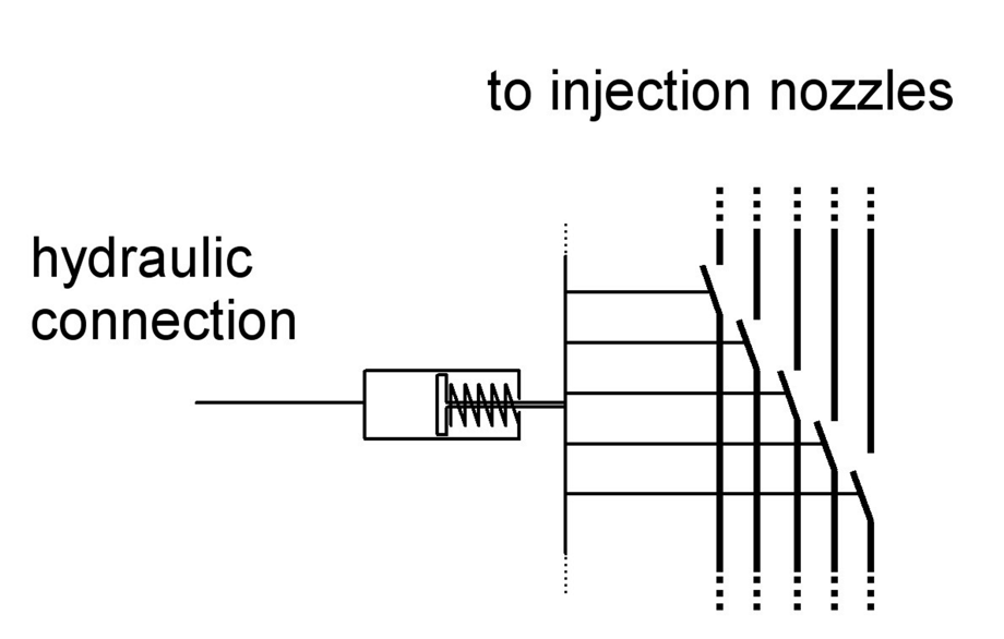
The valve consists of multiple valve cartridges in a circular arrangement.
The cartridges are operated by one common central hydrailic cylinder.
At the initial state the cartridges are closed by the spring force and the pressure load of the fuel.
When the hydraulic cylinder is actuated all the valve cartridges are opened at the same time, to release the flow of the fuel to all combustion chambers.
| Designed For | All GE Fram 5 and GE Frame 6 |
| Number of Elements | 2; 4; 6; 10; 12; 14; 18 |
| Flow Rate per Element | 12.8 l/min (3.4 GPM) at 2400 RPM |
| Operating Pressure | Max 103 bar (1500 psig) |
| Fuel Temperature | Max 130 ºC (266 ºF) |
| Fuels | Distillate, Heavy Fuel, Crude, Naptha |
| Starter Motor | Optional (available in various types. |
VALVE ASSEMBLY
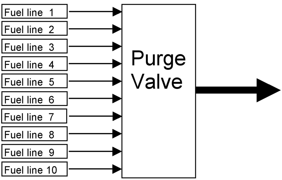
The purge value is used on gas turbines operated on liquid fuel.
The valve consists of a multi ported casing where each port is connected to one fuel line, between the Flow Divier and the nozzle of the gas turbine.
By rotation of a sealing disc all connected lines are either sealed or copened into one common drain connection.
The valve can be operated either hydraulically, manually, or as an alternative pneumatically.
With this purge valve all fuel lines between the Flow Divider and the nozzles can be purged - eg. when the fuel is changed from liquid to gas, or when the turbine is shut down.
| Designed For | All GE Fram 5 and GE Frame 6 |
| Number of Elements | 2; 4; 6; 10; 12; 14; 18 |
| Flow Rate per Element | 12.8 l/min (3.4 GPM) at 2400 RPM |
| Operating Pressure | Max 103 bar (1500 psig) |
| Fuel Temperature | Max 130 ºC (266 ºF) |
| Fuels | Distillate, Heavy Fuel, Crude, Naptha |
| Starter Motor | Optional (available in various types. |
ARE YOU HAVING CORROSION ISSUES?
Please read about our TINOX options